Description
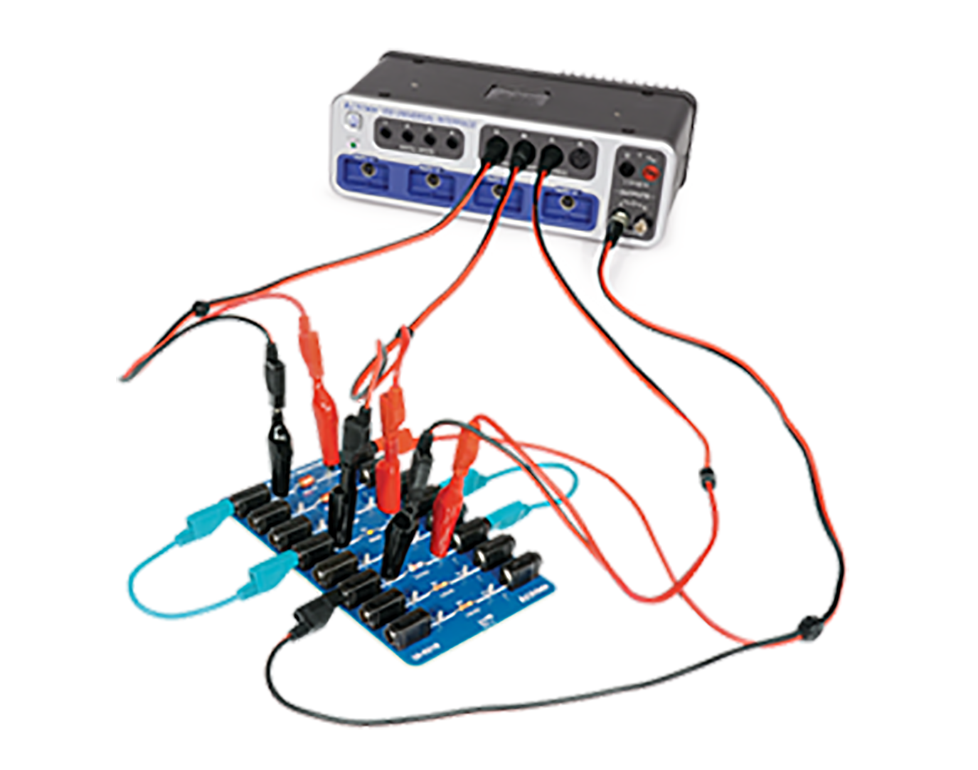
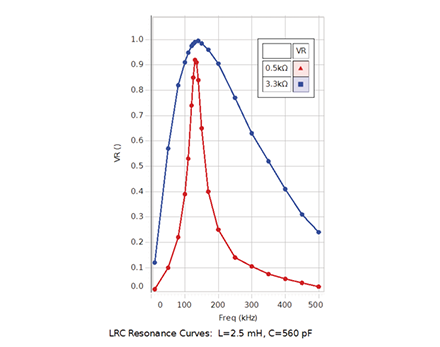
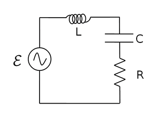
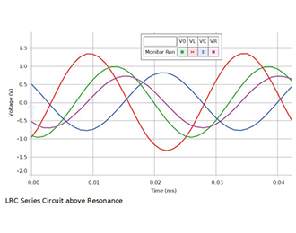
The response of a series LRC circuit is examined at driving frequencies above, below, and at the resonant frequency. A sinusoidal voltage is applied individually to a resistor, a capacitor, and an inductor. The amplitude of the current and the phase difference between the applied voltage and the current are measured in each of the three circuits to see the effect each component has on the current. Finally, a sinusoidal voltage is applied to an inductor, resistor, and capacitor in series. The amplitude of the current and the phase difference between the applied voltage and the current are measured and compared to theory.
Concepts
- LC oscillations
- Inductive, capacitive, and resistive AC circuits
- LRC resonant frequency
Experiments
Includes
- Voltage Sensor (unshrouded) (UI-5100) (3)
- Resistor Capacitor Inductor Network (UI-5210)
- Banana Plug Cord Sets, 30 cm Length (SE-7123)
- BNC Function Generator Output Cable (unshrouded) (UI-5119)
Software Required
This product requires PASCO software for data collection and analysis. We recommend the following option(s). For more information on which is right for your classroom, see our Software Comparison: SPARKvue vs. Capstone »
Interface Required
This product requires a PASCO Interface to connect to your computer or device. We recommend the following option(s). For a breakdown of features, capabilities, and additional options, see our Interface Comparison Guide »


